MIDI Knob Bank
I don’t want to touch a keyboard while holding a guitar!!!
Idea
There are just two main usecases for something like this.
Adjust Ableton Effects live without touching a keyboard or mouse
I’m using Ableton Live to set up solo performances. Sure the looping ability is cool, but changing something like the drive on the vocal effects chain or the compression on background tracks is much easier when its an easily-accessible knob.
Adjust parameters smoothly on the Hydra video synth
Hydra is great for livecoding, when the experience is meant to include the performer’s interaction and creativity when using text to express something. However, in a more traditional concert setting, or one where I’m holding a guitar, there simply isn’t the time or attention span to type and play with values.
Prior Art
Obviously the first thing I thought about was the Korg NanoKontrol.
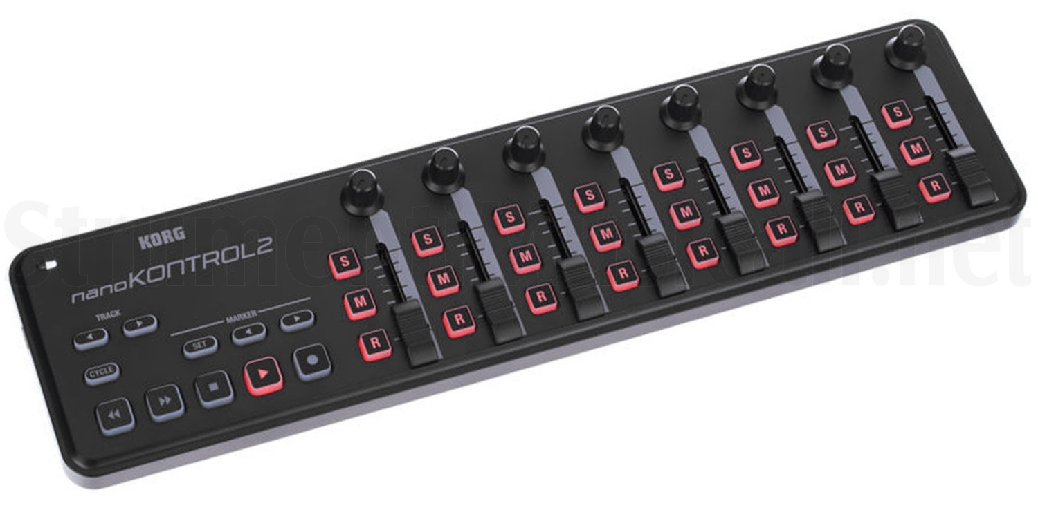
But two things stopped me; I needed two separately addressed devices so ableton and hydra didn’t have to share, and I also wanted a drumpad-like device to control the tracks and scenes.
The concept of building your own midi knob set is not new, many people have done it before. This tutorial basically covered everything I needed - except for the form factor.
Design
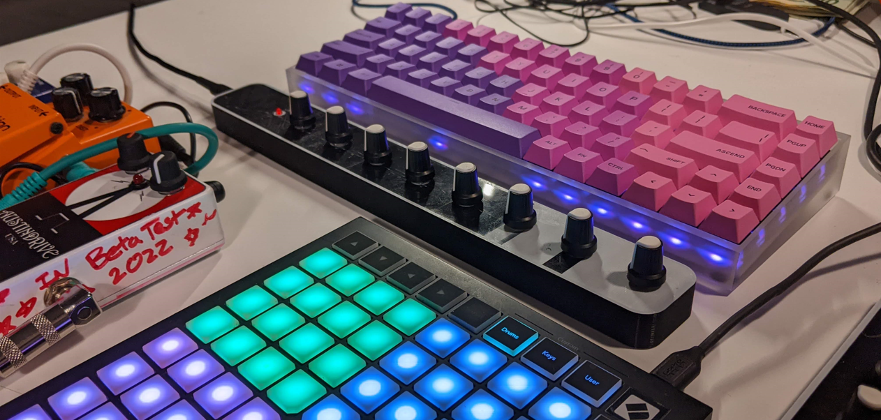
I decided to buy a Novation Launchpad, and construct two knob banks of ??? knobs each. If I really need some sliders, I can build/buy that then.
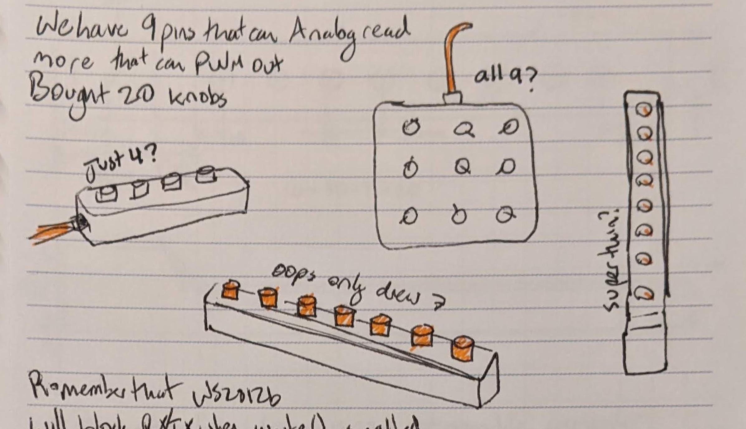
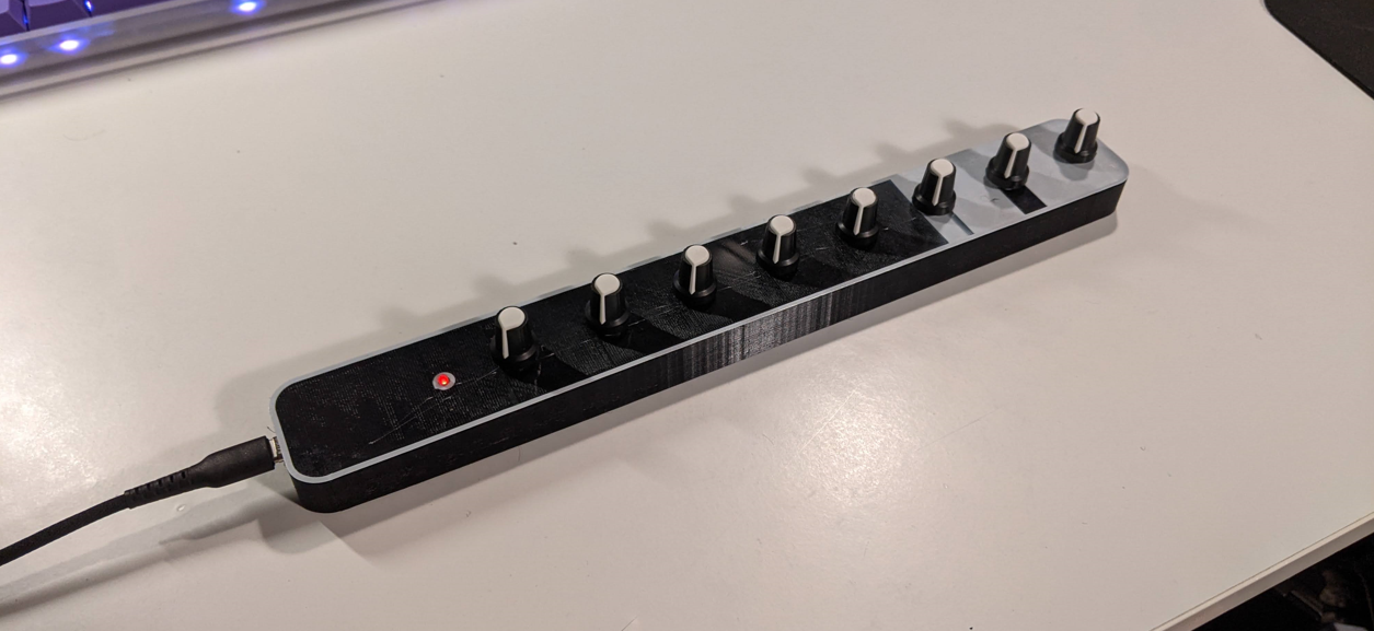
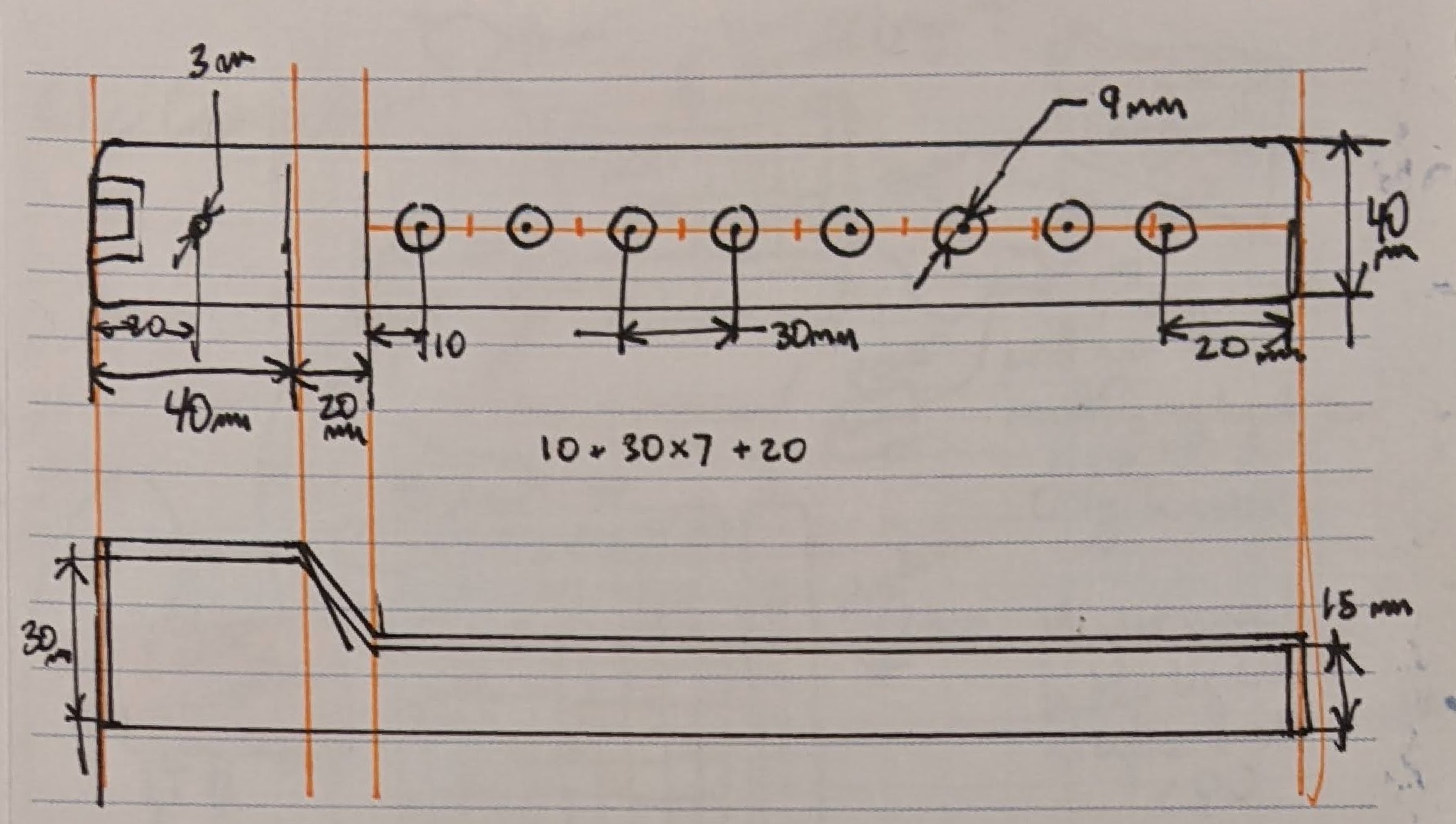
I liked the idea of a super slim row of knobs, that can be oriented however fits your setup. No nonsense, no buttons. I also preferred an extra empty space to fit the microcontroller instead of making the whole thing thicker.
Requirements
- 8 Knobs
- USB Type-C connector
- Native MIDI device (no serial->midi program needed)
Aside about CAD
I started modeling this in blender using the CAD Sketcher Plugin, but found one massive limitation: You cannot reference geometry from a different out-of-plane sketch. Especially if that geometry has since been extruded. By the looks of it, this is a limitation that will never be fixed. The ‘Thicken’ modifier that functions as extrude will forever create meshes, not parameterized geometry. Also, even creating a sketch on a face seems to be missing. This plugin, while awesome, will never match true parameterized modeling (but I will keep using it for my Blender-native projects as needed, to quickly generate properly-sized objects).
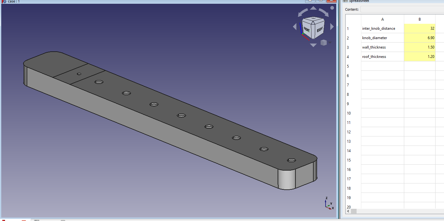
So I opened up FreeCAD, something I had put down about two years ago when I got frustrated after not immediately understanding everything about it. I read their (very helpful) wiki and got to work. It was much easier than I remembered! I must have been drunk or impatient when I tried it the first time. I even used the spreadsheet for named parameters. And I didn’t even need to pirate solidworks!
Hardware
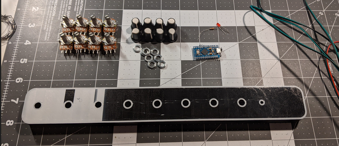
Heres a list of the stuff inside one knob bank:
| Item | Qty. | I paid… |
|---|---|---|
| 3D printed case (0.04 kg) | 1 | $1 |
| Arduino Pro Micro | 1 | $7 |
| B10K Potentiometer | 8 | $5 |
| (optional stuff below) | — | — |
| USB Type C Female Connector | 1 | $1 |
| Mico-USB Male Connector | 1 | — |
| 5V LED | 1 | — |
| 200 Ohm Resistor | 1 | — |
And heres a list of the tools needed:
- Soldering Iron
- Adjustable Crescent Wrench
- Wire cutters/strippers
- Needle-nose pliers
- Hot Glue Gun
- Knife
I also used the Hot Holder Pro, which is pretty cool. I still used the articulated helping hands, and often used them at the same time.
Software
In an uncharacteristic move, I barely changed the code from this awesome instructable. I did add a line to turn on an LED during the setup() so I would know if the board was powered and the microcontroller was working. This was a v2 thing for me, so my first prototype is done and doesn’t have this.
Build
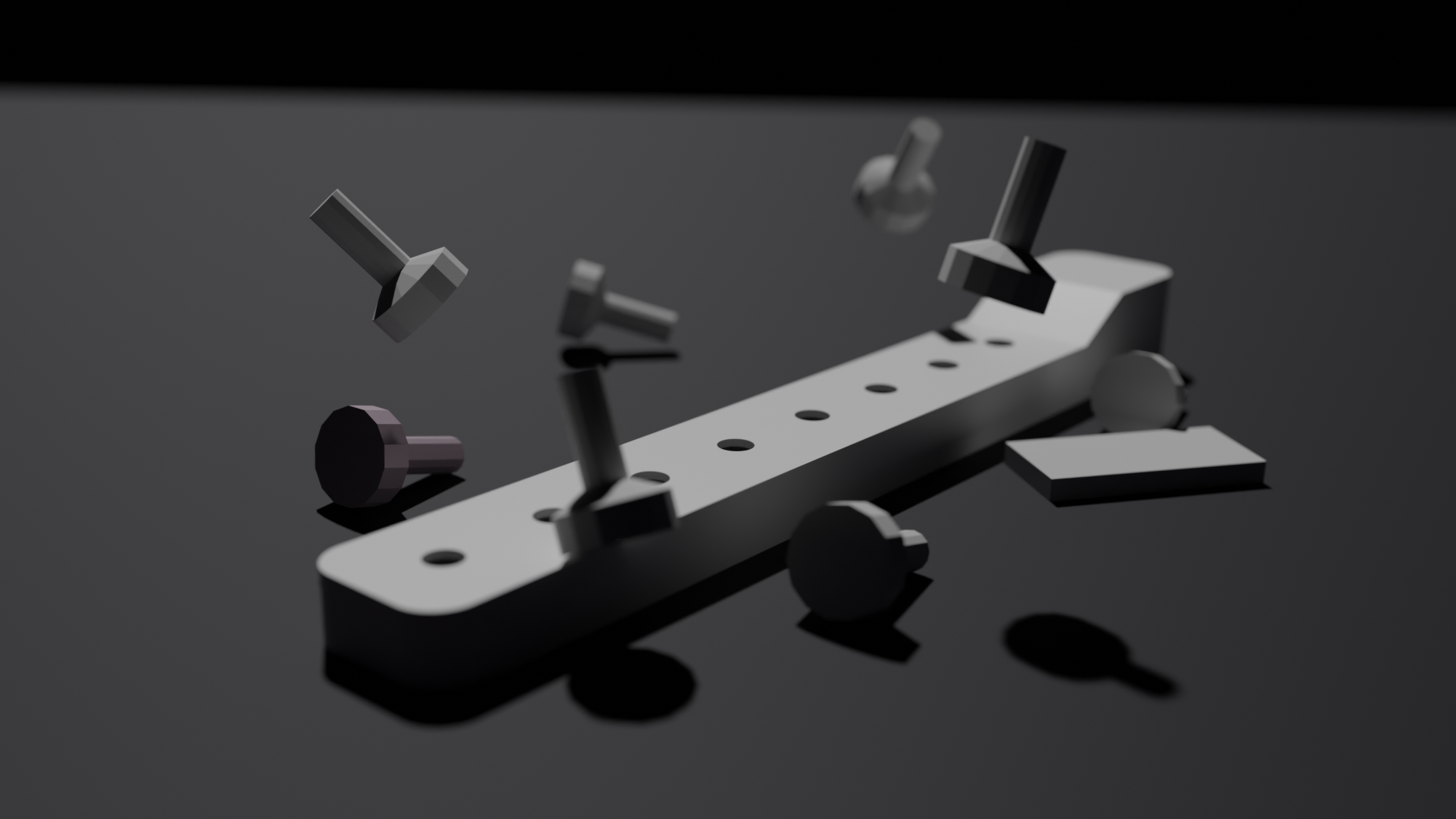
I 3D printed the case. I accidentally got a cool two-tone on my first attempt when I didn’t purge the leftover filament from my bowden tube, but couldn’t quite replicate it on the second try.
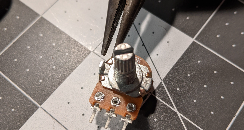
I broke off the positioning tabs on the knobs because I was too lazy to model the little holes for them. Sorry :/.
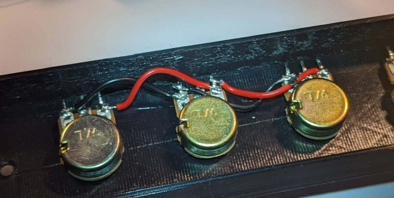
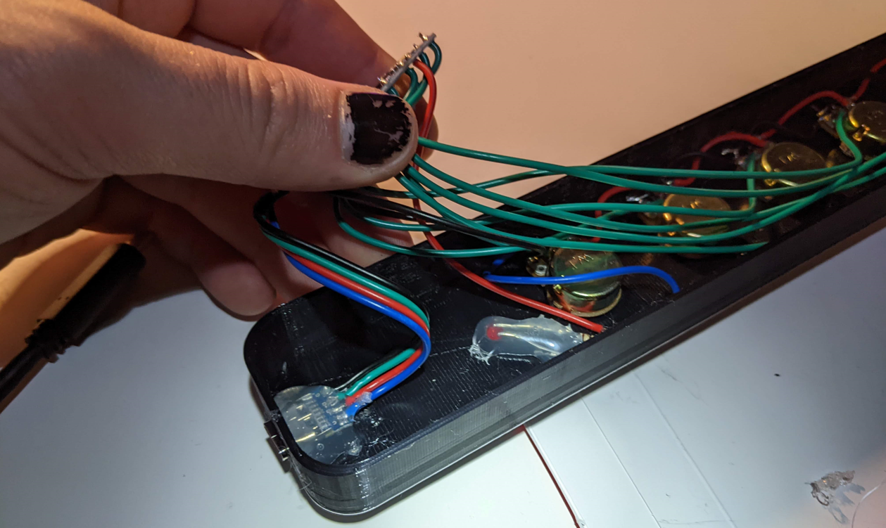
I then installed the pots and started soldering the ground and 5V in a chain. I did this weird over-under pattern to prevent the wires from getting in my way.
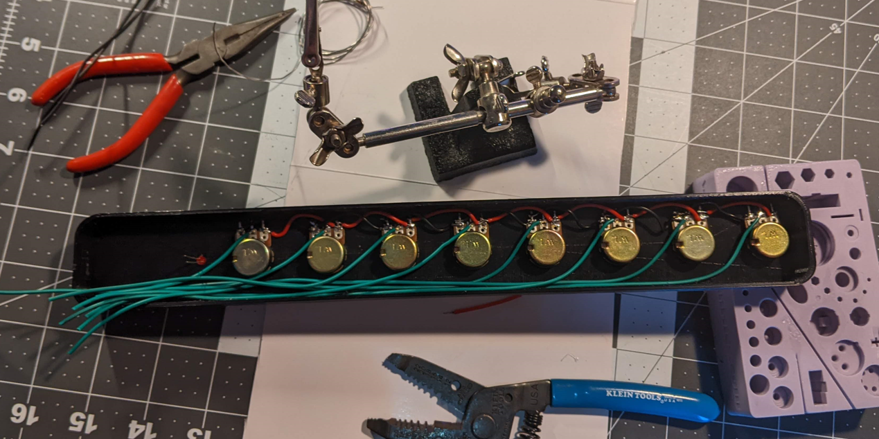
Then I soldered the wires for the out pin of all the pots. I left some slack to be cut later.
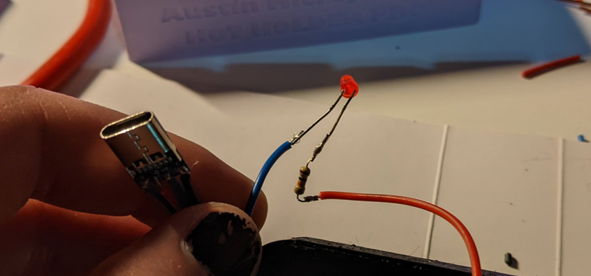
Then I made my adapter from Micro to Type-C
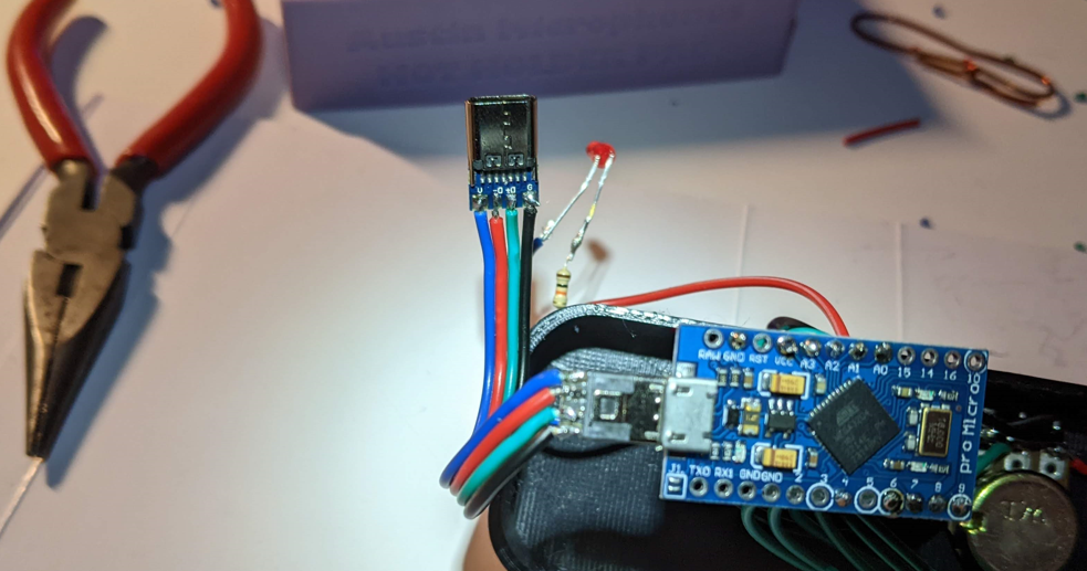
And soldered together the LED and resistor.
I soldered all the connections from the pots to the analog pins, and glued down the Type-C and LED.
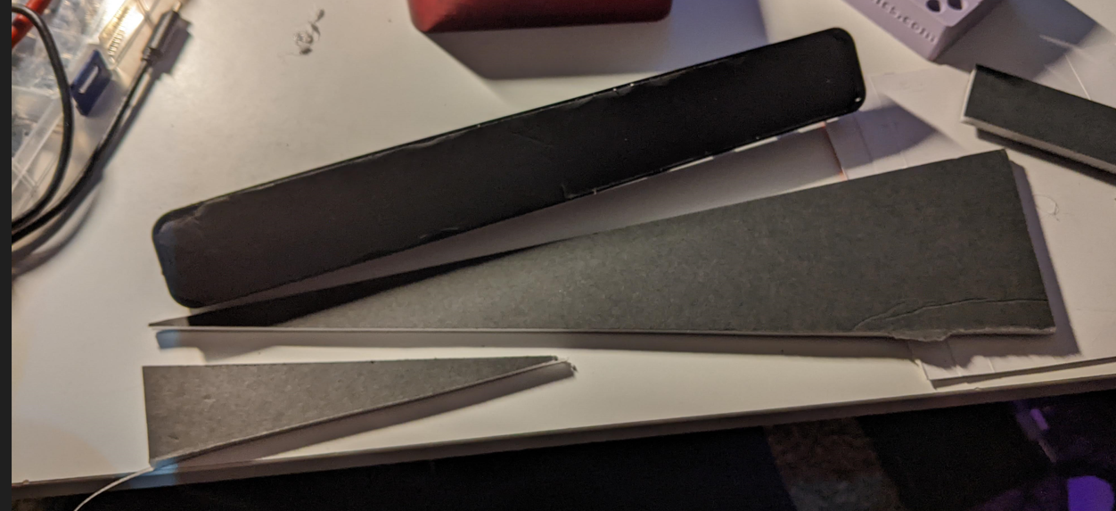
I then cut a backing out of foam board. You could make this out of cardboard, plastic, aluminum, or anything. I cant justify 3D printing something like this.
And it works!